
No, il softstart dipende solo dal condensatore sul gate.
Sostieni il forum con una donazione! Il tuo contributo ci aiuterà a rimanere online!

Dumble-Style SE con GU50: Loop Bilanciato e Finale ad Alta Dinamica
Re: Dumble SE con GU50 (???)
Cosa intendi per dinamica? In ambito chitarristico la dinamica solitamente si ha avendo un po' di compressione agendo sulle velocità di carica e scarica di Vg2. Comunque non cambia molto fra le due opzioni.


Re: Dumble SE con GU50 (???)
Ciao Robi.
Per la rampa:
Io ho notato che cambiando il valore di c3 ( sul tuo schema ) le cose cambiano. Poi non saprei.
Per la dissipazione:
Ho solo testato con il "termometro" entrambi i mosfet. Non ho messo nessun parametro. La classica misura della temperatura che il software ti rileva in watt.
Per la dinamica:
Forse la scelta del termine non é proprio adeguata.
Tempo fa si ragionava sul metodo per scalare la tensione tramite partitore resistivo. Parlandone con te e con Franco, eravamo arrivati alla conclusione che non era un buon metodo per via dell'effetto Sag e altro che poteva influenzare la dinamica.
Credo che sia per la stessa ragione per il quale si preferisce una choke rispetto ad una resistenza.
Mi chiedevo se un qualcosa del genere potesse avvenire con l'impiego di zener o con l'impiego di mosfet quando si limita pesantemente una tensione ed una corrente.
Re: Dumble SE con GU50 (???)
Adesso ho capito. Ci sono un po' troppi schemi che girano
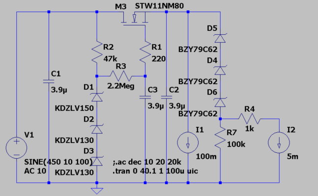
Come dicevo, l'unico condensatore che stabilisce il tempo della rampa insieme col resistore relativo, è quello sul gate del mosfet: R3 C3 nel mio schema.
5x R3 C3 è il tempo di carica.
C1 stabilisce i picchi inferiori del ripple, quindi il margine che dobbiamo tenere per la tensione in ingresso al mosfet (considerando anche le fluttuazioni di rete).
C2 deve solo coprire i picchi e poco più.
Re: Dumble SE con GU50 (???)
Sì, ma hai comunque dei valori di riferimento: tensioni a valle e monte, etc... Sono quelle che vanno definite e da cui dipendono i valori che vedi. Inoltre l'assorbimento cambia all'avvio, e va gestito per ottimizzare il tutto ed evitare pericoli. Intendevo questo.
Re: Dumble SE con GU50 (???)
In realtà in ambito chitarristico un po' di sag su Vg2 serve a dare compressione e quindi l'impressione di maggior volume.Dom ha scritto: ↑14/06/2024, 6:55Forse la scelta del termine non é proprio adeguata.
Tempo fa si ragionava sul metodo per scalare la tensione tramite partitore resistivo. Parlandone con te e con Franco, eravamo arrivati alla conclusione che non era un buon metodo per via dell'effetto Sag e altro che poteva influenzare la dinamica.
Questo, come altre cose, si vedrà meglio col metodo Cutugno.
Re: Dumble SE con GU50 (???)
In realtà dipende molto dall'applicazione, ci sono ampli che hanno resistori al posto degli induttori, e sono diventati iconici (penso ad esempio ai Trainwreck sui boutique, ma anche tutti i Marshall post JCM800).
Re: Dumble SE con GU50 (???)
L'impedenza in entrambi i casi è molto più bassa di un resistore o un induttore, quindi la tensione "copierà meglio" quanto gli imponi. Eventuali cali di tensione in basi ai picchi li gestisci con un resistore in serie, o un RCR se vuoi una determinata velocità di carica e scarica (l'attack e release del compressore, per fare un'analogia).
Re: Dumble SE con GU50 (???)
Riporto qui qualcosa che coi simulatori non si vede: il rumore degli zener (e non solo):
Noise measurements for LEDs and zener diodes
--------------------------------------------
(C) Christer at DiyAudio.com
You are allowed to copy and use this information for your
personal and non-commercial use.
DESCRIPTION OF TEST RIG
-----------------------
The test rig uses three current sources of approx. 1, 5 and 20 mA
built using low-noise BJTs (BC559) to feed the device under test
(DUT) alternatingly. The noise was measured using two op amps in
in non-inverting configuration cascaded, both having a gain of 34,
making a gain of 1156 in total. The first op amp is a very-low-noise
model (LT1115) and uses a gain resistor of only 10 Ohms in the feedback
network. The gain resistor is thus 330 Ohms which works since the op
amp is only expected to output very low-level signals. The second op
amp is a low-noise type (NE5534) with gain and feedback resistors of
100 Ohms and 3.3 kOhms. The output was measured using a PC soundcard
(Creative Audigy LS in 16-bit 44.1 kHz mode). Each measurement consists
of a 10 second capture of the soundcard input and the RMS value for
this 10 s. signal was computed. The program was calibrated (using a
sine wave and an oscilloscope) to give aprroximately correct voltage
readings and all measurements were divided by 1156 to give the equivalent
input RMS noise at the first op amp, ie. at the DUT. No extra filters
except what is on the soundcard were used.
TEST METHOD
-----------
A spectrum of LED types ranging from IR to blue and of approximately
the same type were measured. All LEDS were selected to have an max
If of at least 20 mA, since this current was used in the test. Further
four 0.5W types of zener diodes were tested, two of them (5.6 and 6.8 V)
were deliberately selected close to each other but such that the 5.6 V
diode should be expected to have true zener breakdown and the 6.8 V one
to have avalanche breakdown. The other two were selected to be far away
from this "transition region". Two 1.3W zeners were also tested to see
how the power rating affects noise figures.
For each type of DUT, two devices (denoted #1 and #2 and presumably
from the same batch) were tested at the three test currents 1, 5 and
20 mA and the equivalent noise at the DUT was measured and calculated
as described above. For each combination of device and current, five
10-second measurements were made.
For reference, the voltage drop at each test current
was also measured for one device of each type.
MEASUREMENTS
------------
All values are RMS values
Idle noise:
----------------------------------------------------
Measured idle noise of amplifier with grounded input:
0.19 0.19 0.19 0.19 0.18 uV
(The theoretical max value was calculated to 0.16 uV for
20kHz bandwidth and 0.22 uB for 40 kHz bandwidth).
Measured idle noise of amplifier with 100 Ohm source resistor:
0.26 0.25 0.24 0.26 0.26 uV
(The theoretical max value was calculated to 0.20 uV for
20kHz bandwidth and 0.28 uB for 40 kHz bandwidth).
LEDs:
----------------------------------------------------
(All LEDs of brand Everlight)
IR204/P1 (IR):
#1 @ 1mA: 3.7 3.7 3.7 3.7 3.7 uV
#1 @ 5mA: 0.67 0.66 0.65 0.66 0.66 uV
#1 @ 20mA: 0.24 0.23 0.24 0.23 0.23 uV
#2 @ 1mA: 3.8 3.8 3.7 3.7 3.7 uV (Vf = 1.05 V)
#2 @ 5mA: 0.65 0.64 0.64 0.64 0.64 uV (Vf = 1.11 V)
#2 @ 20mA: 0.24 0.25 0.23 0.24 0.22 uV (Vf = 1.17 V)
EL202HD (red):
#1 @ 1mA: 0.31 0.32 0.31 0.31 0.32 uV
#1 @ 5mA: 0.26 0.26 0.27 0.27 0.27 uV
#1 @ 20mA: 0.39 0.36 0.37 0.36 0.37 uV
#2 @ 1mA: 0.39 0.37 0.38 0.38 0.35 uV (Vf = 1.82 V)
#2 @ 5mA: 0.32 0.30 0.30 0.30 0.31 uV (Vf = 1.89 V)
#2 @ 20mA: 0.41 0.40 0.41 0.41 0.46 uV (Vf = 2.09 V)
EL204ID (red-orange):
#1 @ 1mA: 0.31 0.30 0.31 0.31 0.31 uV
#1 @ 5mA: 0.25 0.26 0.26 0.26 0.24 uV
#1 @ 20mA: 0.41 0.41 0.48 0.40 0.41 uV
#2 @ 1mA: 0.35 0.31 0.29 0.30 0.32 uV (Vf = 1.64 V)
#2 @ 5mA: 0.25 0.26 0.27 0.26 0.30 uV (Vf = 1.74 V)
#2 @ 20mA: 0.40 0.40 0.39 0.40 0.41 uV (Vf = 1.90 V)
EL204YD (yellow):
#1 @ 1mA: 0.42 0.30 0.29 0.29 0.28 uV
#1 @ 5mA: 0.28 0.26 0.25 0.33 0.27 uV
#1 @ 20mA: 0.42 0.39 0.39 0.40 0.40 uV
#2 @ 1mA: 0.31 0.30 0.31 0.30 0.31 uV (Vf = 1.78 V)
#2 @ 5mA: 0.28 0.47 0.28 0.26 0.25 uV (Vf = 1.87 V)
#2 @ 20mA: 0.34 0.34 0.35 0.34 0.34 uV (Vf = 2.02 V)
EL204GD (green):
#1 @ 1mA: 0.68 0.50 0.50 0.47 0.46 uV
#1 @ 5mA: 0.35 0.30 0.28 0.28 0.29 uV
#1 @ 20mA: 0.36 0.35 0.35 0.35 0.35 uV
#2 @ 1mA: 0.46 0.46 0.44 0.44 0.41 uV (Vf = 1.82 V)
#2 @ 5mA: 0.36 0.33 0.32 0.33 0.32 uV (Vf = 1.92 V)
#2 @ 20mA: 0.39 0.40 0.39 0.41 0.40 uV (Vf = 2.12 V)
EL204UBD (blue):
#1 @ 1mA: 4.6 4.5 4.6 4.5 4.6 uV
#1 @ 5mA: 3.2 3.2 3.2 3.2 3.2 uV
#1 @ 20mA: 2.8 2.8 2.7 2.7 2.7 uV
#2 @ 1mA: 4.4 4.4 4.3 4.2 4.3 uV (Vf = 3.26 V)
#2 @ 5mA: 3.1 3.2 3.2 3.1 3.2 uV (Vf = 3.44 V)
#2 @ 20mA: 2.9 2.8 2.8 2.8 2.7 uV (Vf = 3.69 V)
Zeners:
---------------------------------------------------------
(All zeners of brand Temic.)
BZX55/C2V7 (0.5W 2.7V):
#1 @ 1mA: 1.1 1.1 1.1 1.1 1.1 uV
#1 @ 5mA: 1.0 0.88 0.85 0.86 0.87 uV
#1 @ 20mA: 1.0 0.81 0.72 0.72 1.1 uV
#2 @ 1mA: 1.2 1.1 1.1 1.1 1.1 uV (Vr = 2.03 V)
#2 @ 5mA: 0.91 0.88 0.87 0.86 0.85 uV (Vr = 2.50 V)
#2 @ 20mA: 1.1 0.80 0.77 0.73 0.71 uV (Vr = 3.02 V)
BZX55/C5V6 (0.5W 5.6V):
#1 @ 1mA: 5.3 5.3 5.3 5.3 5.3 uV
#1 @ 5mA: 2.9 2.9 2.9 2.9 2.9 uV
#1 @ 20mA: 1.7 1.6 1.6 1.6 1.6 uV
#2 @ 1mA: 5.3 5.3 5.3 5.3 5.3 uV (Vr = 5.68 V)
#2 @ 5mA: 2.9 2.9 2.9 2.9 2.9 uV (Vr = 5.77 V)
#2 @ 20mA: 1.8 1.6 1.6 1.6 1.6 uV (Vr = 5.81 V)
BZX55/C6V8 (0.5W 6.8V):
#1 @ 1mA: 16 16 16 16 16 uV
#1 @ 5mA: 21 21 21 21 21 uV
#1 @ 20mA: 5.8 5.5 5.5 5.5 5.6 uV
#2 @ 1mA: 25 25 25 25 25 uV (Vr = 6.93 V)
#2 @ 5mA: 13 13 13 13 13 uV (Vr = 6.96 V)
#2 @ 20mA: 4.6 4.7 4.5 4.5 4.4 uV (Vr = 7.00 V)
(Rechecked both devices due to their inconsistent
behaviour for 1 and 5mA).
BZX55/C12 (0.5W 12V):
#1 @ 1mA: 0.35 0.37 0.37 0.39 0.39 uV
#1 @ 5mA: 0.30 0.28 0.28 0.28 0.30 uV
#1 @ 20mA: 0.24 0.25 0.25 0.26 0.25 uV
#2 @ 1mA: 0.32 0.33 0.32 0.33 0.32 uV (Vr = 11.32 V)
#2 @ 5mA: 0.26 0.26 0.27 0.32 0.26 uV (Vr = 11.37 V)
#2 @ 20mA: 0.25 0.26 0.28 0.24 0.30 uV (vr = 11.42 V)
BZX85/C2V7 (1.3W 2.7V):
#1 @ 1mA: 0.77 0.77 0.77 0.77 0.76 uV
#1 @ 5mA: 0.62 0.61 0.63 0.61 0.60 uV
#1 @ 20mA: 0.55 0.55 0.54 0.55 0.55 uV
#2 @ 1mA: 0.78 0.78 0.78 0.78 0.78 uV (Vr = 1.30 V)
#2 @ 5mA: 0.62 0.62 0.61 0.62 0.62 uV (Vr = 1.61 V)
#2 @ 20mA: 0.57 0.56 0.57 0.56 0.56 uV (Vr = 1.92 V)
BZX85/C12 (1.3W 12V):
#1 @ 1mA: 0.49 0.53 0.48 0.50 0.52 uV
#1 @ 5mA: 0.54 0.55 0.58 0.46 0.48 uV
#1 @ 20mA: 0.44 0.35 0.38 0.36 0.33 uV
#2 @ 1mA: 0.42 0.43 0.46 0.48 0.41 uV (Vr = 9.84 V)
#2 @ 5mA: 0.40 0.35 0.35 0.37 0.29 uV (Vr = 9.89 V)
#2 @ 20mA: 0.34 0.33 0.31 0.30 0.31 uV (Vr = 9.94 V)
-
Kagliostro

- Amministratore

- Messaggi: 10019
- Iscritto il: 03/12/2007, 0:16
- Località: Prov. di Treviso
Re: Dumble SE con GU50 (???)
Ciao Roberto
al gate del Mosfet è collegato C3
---
Franco
il fatto è che partendo da sinistra ed andando verso destra la numerazione degli elettrolitici non è lineare (almeno in questo schema)No, il softstart dipende solo dal condensatore sul gate.Dom ha scritto: ↑ieri, 19:55
...Se aumentiamo C3, non alziamo anche il tempo della rampa del Soft Starter?
al gate del Mosfet è collegato C3
---
Del resistore in serie mi pare se ne fosse già parlato (come possibile mezzo di alterazione del funzionamento) e mi pare anche che Roberto, da qualche parte, avesse già detto qualcosa sull'uso oculato di un RCR per arrivare a quanto desiderato..... Eventuali cali di tensione in basi ai picchi li gestisci con un resistore in serie, o un RCR se vuoi una determinata velocità di carica e scarica (l'attack e release del compressore, per fare un'analogia).
Franco
Re: Dumble SE con GU50 (???)
Il fraintendimento è nato dal fatto che ho guardato le immagini del post in cui era posta la domanda, e sul cellulare in questo schema:Kagliostro ha scritto: ↑14/06/2024, 9:06il fatto è che partendo da sinistra ed andando verso destra la numerazione degli elettrolitici non è lineare (almeno in questo schema)
download/file.php?id=16232&mode=view ho letto C3 invece era C8.
Il funzionamento l'ho spiegato a pagina 55 (ma credo anche prima EDIT: sì, a pagina 48!):
robi ha scritto: ↑12/06/2024, 0:26Corretto anche questo, possiamo impostare il tempo di salita variando il 5RC che va sul gate del mosfet.Kagliostro ha scritto: ↑11/06/2024, 23:242) Elimina all'accensione sovratensioni superiori a 410V consentendo di usare dopo di lui elettrolitici da 450V anziché da 500V
Re: Dumble SE con GU50 (???)
Nel RCR, il primo RC determina la carica (release) mentre il secondo CR determina (con Ig2) la scarica (attack).Kagliostro ha scritto: ↑14/06/2024, 9:06Del resistore in serie mi pare se ne fosse già parlato (come possibile mezzo di alterazione del funzionamento) e mi pare anche che Roberto, da qualche parte, avesse già detto qualcosa sull'uso oculato di un RCR per arrivare a quanto desiderato
Re: Dumble SE con GU50 (???)
Grazie mille Robi!
Ora mi é molto più chiaro il tutto. Quindi o con zener o con mosfet non cambia molto riguardo a quel discorso di prima.
...riguardo al rumore che non vediamo nei simulatori, ne dovremmo prendere atto? Può essere che in simulazione vediamo un segnale quasi assente di ripple e dopo ci troviamo un po' di ronza o altro dovuto agli zener?
...il listato con i valori lo ho guardato molto di fretta perché sto al lavoro...